Why Functional Testing Matters: Ensuring Membrane Switch Excellence
Functional testing is the final, non-negotiable check that guarantees a membrane switch works reliably, meets design specs, and delivers a standout user experience—critical for protecting your brand and avoiding costly field failures or recalls.
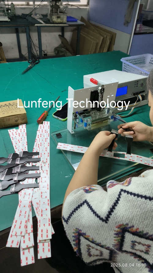
This rigorous process goes beyond basic checks: it simulates real-world use to validate every component (overlay, circuits, LEDs, connectors) working in harmony. Using custom fixtures like "bed of nails," it uncovers defects such as open/short circuits or misaligned parts, ensuring 100% functionality.
Key tests that make the difference:
Continuity & Short Circuit Checks: Verify proper circuit flow and prevent unintended connections, ensuring each button works exactly as it should.
LED/Backlighting Validation: Confirms bright, consistent, and correctly colored illumination—vital for visibility and user trust.
Actuation Force Testing: Ensures the perfect "feel" (e.g., 150±50g). Too little force risks accidental presses; too much feels stiff. We hit the sweet spot every time.
Switch Bounce Control: Uses oscilloscopes to eliminate erratic signals from contact bounce, ensuring smooth, reliable input for your device’s electronics.
In short, functional testing is your guarantee of excellence. It catches issues early, keeps faulty products off the market, and delivers a switch that performs flawlessly—every press, every time. Trust in rigorous testing, and deliver a user experience that sets your product apart.
Applications and Advantages of Membrane Switches
Membrane switches serve as a key interface between humans and electronic devices. A standout benefit is their ability to integrate printed graphics seamlessly—this allows critical operational information to be directly printed on the switch, enhancing usability.
Take a microwave, for instance: the function of each "button" is clearly printed on the switch itself. This feature enables higher information density, as each part of the panel can be labeled explicitly to indicate its purpose, making membrane switches highly practical in various settings.
Membrane switches find applications across a wide range of industries, such as:
Commercial foodservice and refrigeration
HVAC systems
Test and measurement equipment
Medical electronics and OEM medical devices
Portable electronics and consumer products
Agricultural machinery (tractor cabs, farm equipment)
Industrial control systems
Laboratory instruments
Aerospace technology
Control panels
Fitness equipment
Telecommunications devices
Security systems
Quality Control Measures for Metal Dome Switch Arrays
Metal dome switch arrays are indispensable for delivering the crisp, tactile feedback in a wide range of devices, from remote controls to medical equipment. Their reliability and long-term performance rely heavily on strict quality control throughout the manufacturing process, ensuring each button press offers consistent and dependable functionality.
1. Raw Material Inspection: The Foundation of Quality
High-quality metal dome arrays begin with rigorous checks on raw materials.
Stainless steel domes, the core component, are inspected for thickness, hardness, and elasticity to ensure they meet specified force and travel requirements.
Adhesive layers and polyethylene terephthalate (PET) spacers are examined for uniform thickness, strong adhesive strength, and freedom from contaminants that could interfere with electrical contacts.
2. Dimensional and Visual Inspection: Precision in Assembly
Precision is critical during assembly, and automated optical inspection (AOI) systems play a key role here. These systems verify:
The placement and alignment of each dome on the carrier sheet, ensuring perfect centering over corresponding circuit pads on the printed circuit board (PCB).
Critical tolerances such as dome-to-dome spacing, alignment with fiduciary markers, and overall array profile—any deviation can lead to misalignment in final assembly, resulting in non-functional or unreliable switches.
Both automated and manual visual inspections are also conducted to detect cosmetic defects like scratches, dust, or foreign particles that might compromise performance.
3. Functional Testing: Ensuring Performance Reliability
Functional tests are central to quality assurance, simulating real-world use to validate electrical and mechanical performance:
Actuation force: Measured using specialized force gauges, this is the pressure needed to collapse the dome and close the circuit. Results must stay within tight tolerances to ensure a consistent feel for users.
Return force: Tests the dome’s ability to spring back to its original position, preventing a sluggish or "mushy" response.
Contact resistance: Quantifies the resistance of the closed switch, with low, stable levels essential for reliable signal transmission. High or fluctuating resistance can cause intermittent failures.
Life cycle testing: Domes are repeatedly actuated (hundreds of thousands to millions of times) to assess durability. Technicians track changes in actuation force and contact resistance over time to estimate operational lifespan.
4. Environmental Testing: Withstanding Real-World Conditions
To ensure durability in diverse environments, arrays undergo stress tests including exposure to extreme temperatures, high humidity, and thermal shock. These tests identify potential material or design weaknesses that could lead to premature failure in field use.
Summary
Quality control for metal dome switch arrays is a multi-stage process, from raw material checks to functional and environmental testing. Each step is critical to ensuring these components deliver the reliability and tactile experience required by manufacturers and end-users.
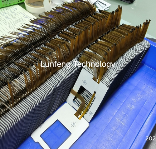
FPC membrane switches are key components in compact, durable electronics, with their assembly involving 8 precise stages to ensure functionality and reliability. Below is a concise breakdown of each step.
1. Material Selection and Inspection
The FPC, pre-fabricated with etched copper circuitry (often gold or nickel/gold plated for durability), undergoes Surface Mount Technology (SMT) if required:
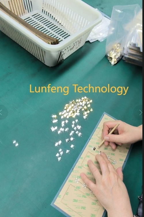
3. Metal/Poly Dome Placement (Tactile Designs)
A spacer (polyester/polyimide with adhesive) with die-cut openings over switch areas is applied. It creates an air gap to prevent accidental actuation, defines actuation travel, and protects internal components.
5. Graphic Overlay Lamination
Flexible FPC tails (with exposed pads/connectors) are terminated via crimped connectors, direct soldering to PCBs, or stiffeners for socket insertion—chosen based on application needs.
7. Electrical Testing and Final Inspection
Continuity/open circuit test: Checks for unintended connections.
Short circuit test: Verifies isolation between circuits.
Switch function test: Confirms correct actuation and signal output (including tactile "snap" feel for domes).
Thank you for choosing Lunfeng Technology—we’re delighted to assist! Proper use of membrane switches, including correct pasting and storage, is key to avoiding damage and extending their lifespan. Below are essential guidelines:
Pasting Steps:
Clean: Ensure the surface (liner, casing, or target area) is smooth, rust-free, oil-free, and dust-free.
Check fit: Position the unpeeled switch at the target area to verify proper sizing.
Align: Peel ~10mm of backing (preferably from a button-free edge), attach to the correct spot, confirm alignment, then proceed.
Apply: Peel and stick gradually, keeping the switch’s curvature ≤15°.
Pasting Notes:
Paste once—no repositioning, as this harms adhesive performance.
Keep curvature ≤15°. Press buttons only when flat; avoid pressing with no liner or when buttons are suspended (may damage metal domes or cause short circuits).
Storage Notes:
Keep the protective transparent films on both sides to prevent scratches on surfaces or display windows.
After removing some from the original package, re-tie the rest loosely as before.
Store tactile products upright to prevent button feedback weakening from long-term pressure.
Protect cables/connectors—do not place them facing down.
Avoid forcefully bending window-equipped or tactile products (may cause short circuits, dome failure, or render the switch useless).
Store at room temperature, away from dust, moisture, and corrosive gases (acidic, alkaline, etc.).
Silkscreen printing excels at applying thick, vivid ink layers to diverse substrates. Equipment ranges from manual setups (requiring skill and effort) to fully automated high-speed lines. Semi-automatic machines strike a key balance: more efficient and consistent than manual options, yet more accessible and flexible than full automation.
Introduction
Semi-automatic silkscreen printers automate the print stroke—driving the squeegee and flood bar across the screen—while needing operators to manually load/unload substrates.
Features
Available in configurations like clamshell, vertical lift, or sliding table, they share core features:
Powered print stroke: Pneumatic/electric actuators move the squeegee and flood bar (no manual effort).
Adjustable pressure: Precise, repeatable settings for squeegee (ink application) and flood bar (pre-filling stencils) ensure uniform prints.
Controlled speed: Electronically/pneumatically set squeegee speed maintains quality across inks of varying viscosity.
Precise off-contact adjustment: Easy tuning of the screen-substrate gap for clean mesh snap-back.
Adjustable stroke length: Custom start/end points optimize cycles for different image sizes.
Integrated registration: X, Y, and often rotational micro-adjustments enable precise multi-color alignment.
Three common materials for graphic overlays are PC, PVC, and PET, with two surface types: matte and glossy.
PC: Boasting good physical and chemical properties, it works with various inks and is the most widely used. Available in both matte and glossy finishes. Matte surfaces, chosen to avoid light interference with control systems, reflect light diffusely (no harsh glare) and hide scratches. Glossy ones, though lacking these traits, have vivid colors—ideal for high-decoration, low-touch scenarios or special display areas like LCD screens.
PVC: Costs about half of PC, cutting production expenses. It has good ductility, allowing 3D patterns via cold pressing. Glossy PVC, usually over 0.5mm thick with water-based paper on both sides, is often used for decorative panels. Matte PVC, under 0.3mm thick, comes as fixed-length sheets (no coils).
PET: Rarely used as its properties are mostly replaceable by PC, except for special needs (e.g., insulation, resilience, solvent resistance). Typically glossy and transparent; a few matte products (e.g., Japan’s Kimoto KB series) have fine surfaces. Unlike PC’s mechanically calendered matte finish, PET’s matte effect is less pronounced.
Introduction
FPC membrane switches are key in modern electronics, merging user interface functions with durable, lightweight designs. Found in medical devices, consumer electronics, and industrial controls, they use a layered structure to sense pressure inputs. With flexibility, customizability, and environmental resistance, they outperform traditional mechanical switches. Below is an overview of their working principle, structure, and advantages.
Basic Structure
FPC membrane switches have multiple layers:
Graphic overlay: Top layer (PET/polycarbonate) with printed icons, protecting internals and enabling user interaction.
Adhesive: Pressure-sensitive, bonding layers while retaining flexibility.
Circuit layer: Core with polyimide substrate and etched copper/silver conductive traces.
Spacer: Polyester film with air gaps, separating circuits to avoid accidental contact.
Bottom circuit/support layer: Rigid/flexible backing for structure; often includes connectors for external devices.
Working Principle
Operation relies on closing an electrical circuit via pressure:
Actuation: Pressing the overlay collapses the spacer’s air gap, bringing top and bottom circuits into contact.
Circuit closure: Conductive traces meet, sending a signal to the device controller.
Tactile feedback (optional): Domes under the overlay provide a "click" for better user experience.
Signal transmission: The FPC’s circuit tail (often with a ZIF connector) sends signals to the PCB.
Polyimide allows repeated flexing, suiting curved/compact designs. Unlike capacitive screens, they need physical pressure, ensuring reliability in high-interference environments.
Materials and Customization
Materials: Polyimide (thermal stability/flexibility), silver/copper traces (low resistance/durability), PET overlay (abrasion/UV resistance), and adhesives (long-term bonding).
Customization: Options include backlighting, embossing, and varied thicknesses for ergonomic/aesthetic needs.
Advantages
Durability: Withstands millions of uses (minimal wear).
Lightweight/thin: Ideal for portables.
Environmental resistance: Sealed against moisture, dust, and chemicals.
Cost-effective: Simplified assembly cuts production costs.
Design flexibility: Fits curved surfaces and complex layouts.
Silkscreen printing is a flexible, time-honored method widely employed to transfer detailed patterns onto acrylic panels, finding use in signage, decoration, and industrial settings. Thanks to its blend of accuracy and sturdiness, it’s perfect for creating vivid, long-wearing graphics. Here’s a breakdown of the the following steps involved in silkscreen printing for Lunfeng Technology acrylic panels:
Designing
Start by crafting designs with vector software such as Adobe Illustrator, which allows for scaling without losing clarity. These designs are then printed onto transparent film to serve as stencils (positives). For prints with multiple colors, each color layer requires its own separate film to make individual screens.
Screen making
A fine mesh screen (usually made of polyester or nylon) is coated with a light-sensitive emulsion. The mesh count, ranging from 110 to 230 threads per inch, depends on how complex the design is—higher counts for intricate designs, lower ones for bold graphics. After coating, the screen is dried in a dark place. The film positive is laid over the emulsion-coated screen, and both are exposed to UV light. This exposure hardens the emulsion everywhere except where the design on the film blocks the light, forming a stencil. The screen is then rinsed with water to wash away the unhardened emulsion, revealing the stencil.
Preparing the acrylic surface
The acrylic panel’s surface must be spotless to ensure the ink adheres properly. Clean it using isopropyl alcohol and a lint-free cloth to get rid of dust, oils, or any leftover residues. For textured or curved acrylic sheets, it’s important to test how well the screen works with the surface beforehand.
Setting up the printing press
The acrylic sheet is fixed onto the printing press bed using clamps or vacuum suction. The screen is positioned above the sheet, and for multi-color prints, precise alignment (registration) is ensured. The off-contact distance—the gap between the screen and the sheet—is adjusted (typically to 1/8 inch) to prevent smudging.
Begin printing
First, select the right ink: options include solvent-based, UV-curable, or acrylic-specific inks, depending on the project’s requirements.
Pour the ink onto the screen above the design area. Use a squeegee to spread the ink evenly across the screen (flood coating) to fill the open mesh.
Hold the squeegee at a 45-degree angle and apply steady, even pressure to transfer the ink through the screen onto the acrylic. For multi-color designs, let each layer dry before moving on to the next.
Ink curing
Proper curing is key to ensuring the ink adheres well and lasts.
For solvent-based inks: Let them air-dry for 10–15 minutes first, then dry them at 120–150°F for 20–30 minutes.
For UV inks: They cure immediately when exposed to UV lamps.
Always follow the manufacturer’s instructions regarding temperature and time to avoid the ink cracking or peeling.
Quality check and finishing touches
Examine the acrylic panel for flaws like bubbles, streaks, or misalignment. Test the ink’s adhesion by gently scratching the edge of the print with a fingernail. If necessary, add a clear acrylic laminate to shield the design from scratches and fading caused by UV rays.
Membrane switches, common in modern electronics, rely heavily on material selection for their upper and lower circuit layers, which consist of flexible substrates with printed conductive inks. Key factors in material choice include conductivity, durability, environmental resistance, and cost.
Substrates
PET: The most popular substrate, offering good dimensional stability, chemical/moisture resistance, flexibility, a smooth printing surface, and low cost—ideal for high-volume production.
PEN: A more expensive alternative with higher thermal and chemical resistance, suited for extreme environments.
PI-based FPCs: Highly flexible, withstanding high temperatures and complex 3D shapes. Using etched copper traces for high conductivity, they are costly and reserved for specialized applications.
Conductive Inks
Silver-based ink: Widely used for excellent conductivity, with silver particles in a polymer binder. Often covered with carbon ink to protect against moisture and silver migration.
Carbon ink: Less conductive but durable, chemical-resistant, and wear-resistant. Graphite inks may also be used alone (for lower conductivity needs) or with silver, balancing conductivity, cost, and durability.
Conclusion
Material choice is key to membrane switch performance. PET dominates as a substrate, while silver and carbon inks are mainstays for circuits. Established materials, alongside new advancements, keep membrane switches vital in electronics.