Introduction
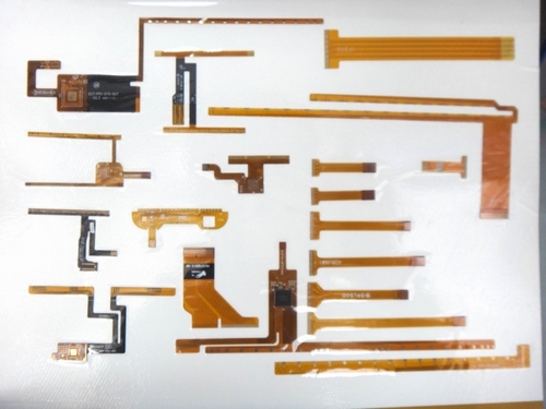
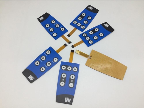
FPC membrane switches are key in modern electronics, merging user interface functions with durable, lightweight designs. Found in medical devices, consumer electronics, and industrial controls, they use a layered structure to sense pressure inputs. With flexibility, customizability, and environmental resistance, they outperform traditional mechanical switches. Below is an overview of their working principle, structure, and advantages.
Basic Structure
FPC membrane switches have multiple layers:
Graphic overlay: Top layer (PET/polycarbonate) with printed icons, protecting internals and enabling user interaction.
Adhesive: Pressure-sensitive, bonding layers while retaining flexibility.
Circuit layer: Core with polyimide substrate and etched copper/silver conductive traces.
Spacer: Polyester film with air gaps, separating circuits to avoid accidental contact.
Bottom circuit/support layer: Rigid/flexible backing for structure; often includes connectors for external devices.
Working Principle
Operation relies on closing an electrical circuit via pressure:
Actuation: Pressing the overlay collapses the spacer’s air gap, bringing top and bottom circuits into contact.
Circuit closure: Conductive traces meet, sending a signal to the device controller.
Tactile feedback (optional): Domes under the overlay provide a "click" for better user experience.
Signal transmission: The FPC’s circuit tail (often with a ZIF connector) sends signals to the PCB.
Polyimide allows repeated flexing, suiting curved/compact designs. Unlike capacitive screens, they need physical pressure, ensuring reliability in high-interference environments.
Materials and Customization
Materials: Polyimide (thermal stability/flexibility), silver/copper traces (low resistance/durability), PET overlay (abrasion/UV resistance), and adhesives (long-term bonding).
Customization: Options include backlighting, embossing, and varied thicknesses for ergonomic/aesthetic needs.
Advantages
Durability: Withstands millions of uses (minimal wear).
Lightweight/thin: Ideal for portables.
Environmental resistance: Sealed against moisture, dust, and chemicals.
Cost-effective: Simplified assembly cuts production costs.
Design flexibility: Fits curved surfaces and complex layouts.
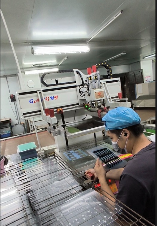
Silkscreen printing is a flexible, time-honored method widely employed to transfer detailed patterns onto acrylic panels, finding use in signage, decoration, and industrial settings. Thanks to its blend of accuracy and sturdiness, it’s perfect for creating vivid, long-wearing graphics. Here’s a breakdown of the the following steps involved in silkscreen printing for Lunfeng Technology acrylic panels:
Designing
Start by crafting designs with vector software such as Adobe Illustrator, which allows for scaling without losing clarity. These designs are then printed onto transparent film to serve as stencils (positives). For prints with multiple colors, each color layer requires its own separate film to make individual screens.
Screen making
A fine mesh screen (usually made of polyester or nylon) is coated with a light-sensitive emulsion. The mesh count, ranging from 110 to 230 threads per inch, depends on how complex the design is—higher counts for intricate designs, lower ones for bold graphics. After coating, the screen is dried in a dark place. The film positive is laid over the emulsion-coated screen, and both are exposed to UV light. This exposure hardens the emulsion everywhere except where the design on the film blocks the light, forming a stencil. The screen is then rinsed with water to wash away the unhardened emulsion, revealing the stencil.
Preparing the acrylic surface
The acrylic panel’s surface must be spotless to ensure the ink adheres properly. Clean it using isopropyl alcohol and a lint-free cloth to get rid of dust, oils, or any leftover residues. For textured or curved acrylic sheets, it’s important to test how well the screen works with the surface beforehand.
Setting up the printing press
The acrylic sheet is fixed onto the printing press bed using clamps or vacuum suction. The screen is positioned above the sheet, and for multi-color prints, precise alignment (registration) is ensured. The off-contact distance—the gap between the screen and the sheet—is adjusted (typically to 1/8 inch) to prevent smudging.
Begin printing
First, select the right ink: options include solvent-based, UV-curable, or acrylic-specific inks, depending on the project’s requirements.
Pour the ink onto the screen above the design area. Use a squeegee to spread the ink evenly across the screen (flood coating) to fill the open mesh.
Hold the squeegee at a 45-degree angle and apply steady, even pressure to transfer the ink through the screen onto the acrylic. For multi-color designs, let each layer dry before moving on to the next.
Ink curing
Proper curing is key to ensuring the ink adheres well and lasts.
For solvent-based inks: Let them air-dry for 10–15 minutes first, then dry them at 120–150°F for 20–30 minutes.
For UV inks: They cure immediately when exposed to UV lamps.
Always follow the manufacturer’s instructions regarding temperature and time to avoid the ink cracking or peeling.
Quality check and finishing touches
Examine the acrylic panel for flaws like bubbles, streaks, or misalignment. Test the ink’s adhesion by gently scratching the edge of the print with a fingernail. If necessary, add a clear acrylic laminate to shield the design from scratches and fading caused by UV rays.
Membrane switches, common in modern electronics, rely heavily on material selection for their upper and lower circuit layers, which consist of flexible substrates with printed conductive inks. Key factors in material choice include conductivity, durability, environmental resistance, and cost.
Substrates
PET: The most popular substrate, offering good dimensional stability, chemical/moisture resistance, flexibility, a smooth printing surface, and low cost—ideal for high-volume production.
PEN: A more expensive alternative with higher thermal and chemical resistance, suited for extreme environments.
PI-based FPCs: Highly flexible, withstanding high temperatures and complex 3D shapes. Using etched copper traces for high conductivity, they are costly and reserved for specialized applications.
Conductive Inks
Silver-based ink: Widely used for excellent conductivity, with silver particles in a polymer binder. Often covered with carbon ink to protect against moisture and silver migration.
Carbon ink: Less conductive but durable, chemical-resistant, and wear-resistant. Graphite inks may also be used alone (for lower conductivity needs) or with silver, balancing conductivity, cost, and durability.
Conclusion
Material choice is key to membrane switch performance. PET dominates as a substrate, while silver and carbon inks are mainstays for circuits. Established materials, alongside new advancements, keep membrane switches vital in electronics.